You are not logged in.

1

Thursday, October 12th 2006, 11:50am

Fabrica Militar de Aviones Aircraft

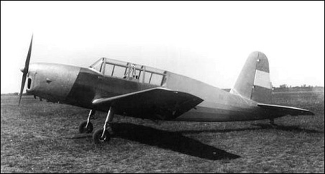
Fabrica Militar de Aviones (FMA) is the main state-owned aircraft manufacturer in Argentina and has been in operation since 1927 with its main factory in the capital city Cordoba. The current Director, since 1943, is Mayor de Aero Ing. Juan Ignacio San Martin and the Chief Designer is Luis Barron.
Previous products were licence-built Avro 504K aircraft, Bristol F.2B two-seat aircraft for the ground-attack role, Dewoitine D.21 fighters and a couple of one-off prototype trainers.

Divisions

Fábrica de Motores de Aviación (Aviation Engine Factory)
FMA brought the Roth-Packard series of radial engines in 1934; the 235hp Roth 7 cylinder single row radial engine, 700hp Roth-Packard 14 cylinder double radial engine and the 650hp Roth 9 cylinder single row radial which were marketed as the 235hp FMA RR-7-1, 700hp FMA RR-14-2 and the 650hp RR-9-1. Development from late 1935 resulted in two new models, the 750hp RR-14-2-D and the 255hp RR-7-1-B. In 1938 the RR-9-1 was up-rated to 675hp and fitted with an automatic pitch changing three-bladed propeller as the RR-9-1-B. Also in 1938 the 715hp FMA RR-14-2-B appeared. This was further modified as the 735hp RR-14-2-C in 1942.

The current range of engines is:
1940 450hp El Gaucho R-1/1 9-cylinder radial
1944 740hp El Indio R-2/1 9-cylinder radial
1947 840hp El Indio R-2/2 9-cylinder radial

Fábrica de Motores a Reacción (Jet Engine Factory)
Created in 1948 in partnership with British firm Rolls-Royce to undertake maintenance and overhaul work on Rolls-Royce Derwent engines for the Meteor fleet. V. Ing. Raúl Argentino Magallanes was appointed as Director. Machine tools and gauges and equipment enable the factory to build component parts locally with assistance from Rolls-Royce technicians and training.

La Fábrica de Hélices y Accesorios (Propellers and Accessories Factory)
Formed in 1948 as another division to take over running of the propeller workshop which had been part of the Cordoba factory since 1928.

Fábrica de Instrumentos y Equipos (Instruments and Equipment Factory (FIE))
Founded in 1948 to manufacture a wide range of instruments, including Sperry equipment under licence, and electronic equipment. Captain Carlos Pedro Porucini was appointed as Director. It replaces the Taller de Reparación de Instrumentos de Aviación (Aviation Instruments Repair Workshop) which had been founded in 1938.

Fábrica de Máquinas y Herramientas (Machines and Tools Factory)
Founded in 1948 as a separate division, originally it was part of the Engine Department in an adjoining workshop which was opened in 1931. Its products are manufactured for the aviation, locomotive and automotive industries in Argentina.

Dirección General de Fábricas la Escuela de Aprendices (Directorate General Factory School Apprentices)
Founded in 1948 by the Director of the Institute Aerotécnico to formally organise the apprentice training programme. The first class enrolled 270 apprentices and by 1949 there were 536.

División Proyectos Especiales (Special Projects Division)
Founded on 12 August 1947 to oversee all of FMA’s rocket programmes.

This post has been edited 5 times, last edit by "Hood" (Jun 8th 2013, 3:13pm)

2

Monday, March 1st 2010, 6:31pm


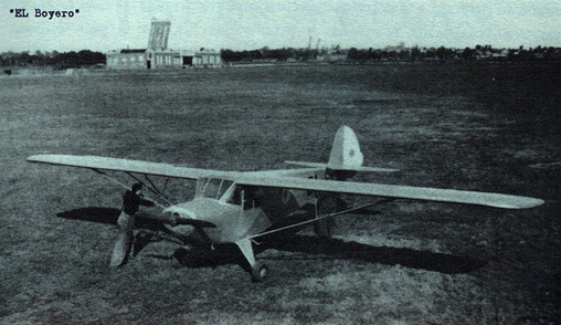
I.Ae.20 El Boyero (The Herdsman)
Designed in late 1938 by three student designers studying at the Cordoba Technical School after studying the latest American cabin monoplanes and first flown in mid 1939 as a two-seat light cabin aircraft for club use and with a secondary role as an air force liaison aircraft. 150 have been ordered by the Ministry of Transport for Argentine aero clubs which will take 100 and the balance of the order will go to the air force as spotter and patrol aircraft. The type is available for private sales as well.
Dimensions: span 11.5m; length 7.1m; height 1.81m; wing area 17.7 sq m; wing loading 31.07kg/ sq m; power loading 8.46kg/hp
Structure: steel-tube fuselage truss with forward fuselage light alloy fuselage covering with fabric aft of the firewall, light alloy used for tail and tailplane construction with fabric covering. High-position wing with light alloy spars and stringers with piano wire internal bracing with wooden ailerons with fabric covering. Rudder and elevators aluminium framed with fabric covering. Simple fixed main undercarriage with mechanical brakes and a non-retractable tail wheel.
Weights: empty 325kg; gross weight 550kg and payload 225kg
Powerplant: one 65hp Continental A65-8 with a Fenolizada wooden two-blade propeller
Performance: max speed 100mph; range 400 miles and service ceiling 13,100ft
Capacity: pilot and passenger seated side-by-side in a cabin with dual-controls
Equipment: full controls and navigation equipment including a radio receiver/transmitter.

This post has been edited 1 times, last edit by "Hood" (Mar 12th 2011, 3:19pm)

3

Sunday, March 6th 2011, 3:09pm

FMA T-514 and Llama

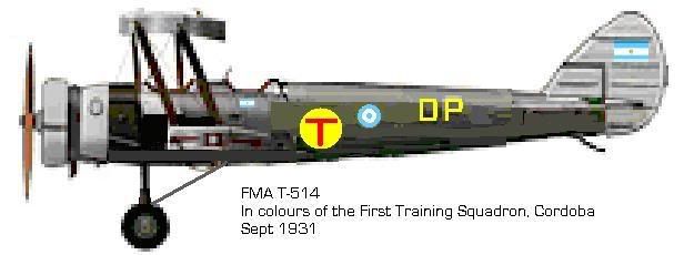
FMA T-514


Being based on the license built Avro 504 the 514 had new undercarriage, new rear fuselage and improved fuel capacity. 30 entered service with two training squadrons, the Commando de Aviacion Naval Argentina ordered 15 in 1932, 144 were built for Brazil and a license was been granted to Mexico.

Dimensions: span 10.99m; length 9.11m; height 3.18m; wing area 30.69m sq
Weights: empty 710kg; max take-off 1110kg
Powerplant: one 150hp Armstrong Genet Major 1A radial
Performance: max speed 115mph; service ceiling 15,000ft; range 290 miles
Capacity: pupil and tutor in tandem


FMA Llama
A light aircraft designed by three young student designers studying at the Cordoba Technical School. This is a light single-seat basic monoplane with a pod and boom fuselage and usher engine on a high monoplane wing. No offical interest was fortcoming.
Dimensions: span 8m; length; height; wing area
Powerplant: one FMA 25hp flat-two-cylinder two-stroke engine
Performance: max speed 65mph; range 130 miles
Capacity: two crew side-by-side

4

Sunday, March 6th 2011, 3:13pm

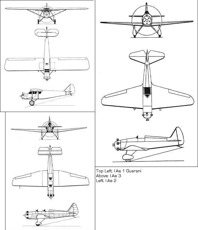
I.Ae 1, I.Ae 2 and I.Ae 3


FMA I.Ae 1 Guarani
Variants include civil I.Ae 1A, the military four seat courier I.Ae 1B (Commando de Aviacion Naval Argentina ordered four), flying ambulance I.Ae 1C with space for one stretcher, pilot and one attendant or walking wounded and a seaplane version with floats I.Ae1D.

Dimensions: span 12.8m; length 8m; height 2.48m; wing area 23m sq
Weights: empty 815kg; max take-off 1,390kg
Powerplant: one 200hp Wright J-4A radial
Performance: max speed 120mph; service ceiling 14,000ft; range 621 miles
Capacity: pilot and three passengers in fully enclosed cabin
Structure: steel-tube fuselage truss with metal forward fuselage and aft doped fabric covering. Wings have wooden spars and ribs with wooden leading edge and fabric covering.
Equipment: cabin is heated and provided with two air ventilation inlets; cabin is well furnished and sound-proofed. Comprehensive instrumentation and compass are fitted as standard.

FMA I.Ae 2
This advanced monoplane entered service in late 1932 and equipped three Fuerza Aerea Argentina flying school squadrons (45 aircraft) and one Commando de Aviacion Naval Argentina training squadron (12 aircraft).

Dimensions: span 10.2m; length 6.85m; height 3.19m; wing area 16.88 sq
Weights: empty 510kg; max take-off 855kg
Powerplant: one 200hp Wright J-4A radial
Performance: max speed 142mph; service ceiling 10,500ft; range 550 miles
Capacity: pupil and tutor in tandem
Structure: steel-tube fuselage truss with light alloy forward fuselage covering and fabric aft, light alloy used for tail construction and fabric covering. The wings are wooden with fabric covering with a plywood leading edge. Simple pneumatic flaps are fitted
Equipment: full dual controls and space for future radio receiver/transmitter; a comprehensive navigation suite is fitted with compass and provision for future HF/DF set.

FMA I.Ae 3
Designed for advanced flying training for fighter pilots the I.Ae is a modern aircraft. It equipped two Fuerza Aerea Argentina flying school squadrons (30 aircraft) from early 1933.

Dimensions: span 7.35m; length 5.75m; height 3.06m; wing area 12.58 sq
Weights: empty 505kg; max take-off 555kg
Powerplant: one 200hp Wright J-4A radial
Performance: max speed 160mph; service ceiling 17,000ft; range 350 miles
Armament: Provision for one 7.7mm MG in forward fuselage and two 25kg bombs
Capacity: pupil in open cockpit
Structure: steel-tube fuselage truss with light alloy forward fuselage covering and fabric aft, light alloy used for tail construction and tailplane covering. The wings are wooden with plywood covering to the aft spar, fabric covers the rest. Simple pneumatic flaps are fitted.
Equipment: full controls and navigation equipment are fitted with space for future radio receiver/transmitter and HF/DF set.

From 1934 the FMA I.Ae 1, FMA I.Ae 2 and FMA I.Ae 3 were offered with the new 235hp FMA RR-7-1 radial engine.

5

Sunday, March 6th 2011, 3:16pm

I.Ae 4 Series

FMA I.Ae 4 Courier
Designed by Luis Barron for a new class of civil-owned mail carriers this fast monoplane is designed for long-range fast mail runs. The outer 2m of each wing folds upwards to save hangar space aboard the ships and US arrestor gear is fitted below the rear fuselage. Instead of mail four passengers could be carried in bucket seats. The Compania Argentina de Marinanavegacion Rividavia ordered twelve for delivery during late 1934. Only around six are now in service.

Dimensions: span 12.19m; length 9.37m; height 3.57m
Structure: Metal monocoque fuselage, metal wing with aluminium spars, wooden ailerons and flaps with fabric covering. Rudder and elevators aluminium framed with plywood covering. Retractable main undercarriage with a non-retractable castoring tail wheel
Weights: Empty 2377lbs; maximum take-off 3628lbs
Powerplant: two 710hp Wright SGR-1820-F3 radials
Performance: max speed 247mph; service ceiling 25,300ft; range 553 miles
Capacity: Pilot and navigator in enclosed cockpit forward; 1500lbs mail in hold in fuselage
Equipment: full controls and navigation equipment including receiver/transmitter, HF/DF set and Sperry autopilot


FMA I.Ae 4R Racer
A modified Courier with non-folding wings of shorter span and a modified fuselage to cut drag. More powerful Atlantean engines are fitted for better high-altitude speed. Only one prototype was built but the Air Force brought three more as trainers.

Dimensions: span 10.6m; length 9.08m; height 3.57m
Structure: Metal monocoque fuselage, metal wing with aluminium spars, wooden ailerons and flaps with fabric covering. Rudder and elevators aluminium framed with plywood covering. Retractable main undercarriage with a non-retractable castoring tail wheel
Weights: Empty 2666lbs; maximum take-off 4082lbs
Powerplant: two 1000hp Ripon R-1000-010RS radials
Performance: max speed 271mph; service ceiling 26,500ft; range 1210 miles
Capacity: Pilot and navigator in enclosed cockpit forward; Elsan and small bunk behind
Equipment: full controls and navigation equipment including two receiver/transmitter sets, HF/DF set and Sperry Gyroscopic Automatic Pilot


FMA I.Ae 4S
Designed initially for Brazil who placed an initial order for seven of the I.Ae 4S, with an option for an additional twenty ( exercised after flight testing and when a carrier actually became available). Mexico ordered 20 land-based and 5 carrier-based I.Ae.4S plus a licence in Q4/34. In Q1/35 Philippines ordered 120 I.Ae 4S. C/N numbers are; Brazil C/N01001-01007, Mexico C/N02001-02020 03001-03005 and Philippines C/N04001-04120. The Naval Avation did not buy any for their new carriers as was suppoed at the time.

Dimensions: span 12.19m; length 9.37m; height 3.57m
Structure: Metal monocoque fuselage, metal wing with aluminium spars, wooden ailerons and flaps with fabric covering. Wing folding with hydraulic assistance fitted to carrier-capable aircraft. Rudder and elevators aluminium framed with aluminium covering. Retractable main undercarriage with a non-retractable castoring tail wheel and arrestor hook on carrier-based examples
Weights: Empty 5788lbs; maximum take-off 8500lbs
Powerplant: two 700hp FMA RR-14-2 radials
Performance: max speed 251mph; service ceiling 23,000ft; range 488 miles
Capacity: Pilot and navigator in enclosed cockpit forward
Armament: three 7.62mm Browning machine guns in the lower nose, 1500lbs of bombs in bay in lower centre fuselage or one 18-21in torpedo on a ventral external rack
Equipment: full controls and navigation equipment including receiver/transmitter, HF/DF set, one flare chute, one optional ventral camera and Sperry Gyroscopic Automatic Pilot

6

Sunday, March 6th 2011, 3:19pm

M.B.2 Bomber and I.Ae 5 Airliner

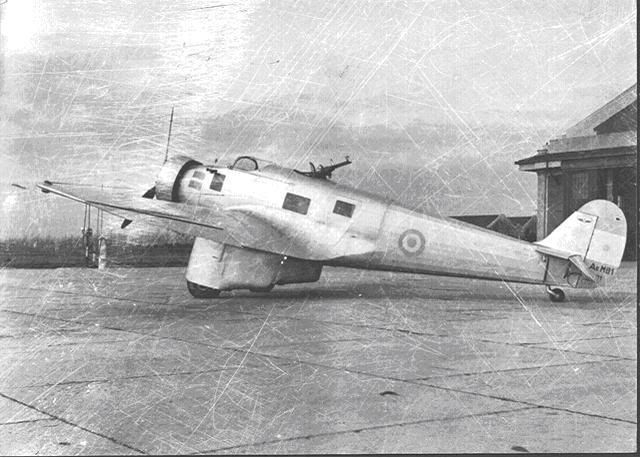
FMA M.B.2


Developed from the I.Ae 5 this militarised version took priority and flew first. Seventy-two were built as bombers for delivery from late 1934. 72 aircraft were built in four batches (18 aircraft each) and all were delivered by Jan 1935. Construction numbers are C/N01001-C/N04018. The M.B.2A will be reserved for a modified variant, the B is a navigation and radio trainer with pilot and instructor with two pupils in the fuselage and fourteen were built during 1935.

Dimensions: span 17.2m; length 10.90; height 2.8m; wing area 35 sq m; wing loading 100kg/ sq m; power loading 5.14kg/hp
Structure: steel-tube fuselage truss with light alloy forward fuselage covering and fabric aft, light alloy used for tail construction and tailplane covering. Metal wing with steel spars, all-metal split flaps and wooden ailerons with fabric covering. Rudder and elevators aluminium framed with fabric covering. Fixed main undercarriage in spats with a non-retractable castoring tail wheel
Weights: empty 2120kg, maximum take-off 3500kg
Powerplant: one 715hp Wright SGR-1820-F3 radial
Performance: max speed 177mph; service ceiling 19865ft, time to 5000m (16,400ft) 37 minutes; range 372 miles
Capacity: pilot in enclosed cockpit forward, navigator/bomb aimer behind in fuselage, radio operator/gunner in rear fuselage, four fuselage windows give all-round vision and the forward windows give the pilot good downward vision for landing.
Armament: one dorsal turret with one 7.7mm Browning MG, one ventral mount with one 7.7mm Browning but capable of mounting a 13mm Browning as an alternative for strafing, bombload 400kg (880lbs) in one lower fuselage and two inner wing bays
Equipment: full controls and navigation equipment including receiver/transmitter, HF/DF set and Sperry autopilot, camera can be fitted in cabin floor, one flare chute, simple mechanical bombsight


FMA I.Ae 5
The airliner version of the M.B.2 for internal routes with rough field performance. Aeravias Argentinas S.A. has ordered four for delivery in 1935 but these were dealyed owing to the South American War. After the war 16 were ordered.

Dimensions: span 17.2m; length 10.90; height 2.8m; wing area 35 sq m; wing loading 100kg/ sq m; power loading 5.14kg/hp
Structure: steel-tube fuselage truss with light alloy forward fuselage covering and fabric aft, light alloy used for tail construction and tailplane covering. Metal wing with steel spars, all-metal split flaps and wooden ailerons with fabric covering. Rudder and elevators aluminium framed with fabric covering. Fixed main undercarriage in spats with a non-retractable castoring tail wheel
Weights: empty 2120kg, maximum take-off 3500kg
Powerplant: one 715hp Wright SGR-1820-F3 radial
Performance: max speed 177mph; service ceiling 19865ft, time to 5000m (16,400ft) 37 minutes; range 452 miles
Capacity: pilot and navigator in enclosed cockpit forward, five passengers in cabin
Equipment: full controls and navigation equipment including receiver/transmitter, HF/DF set and Sperry autopilot

7

Sunday, March 6th 2011, 3:24pm

The Postwar Civil Series

FMA I.Ae 6T
Developed during 1936-37 to replace the T-514 in the basic trainer role the FAA ordered 24 with options on a further 24. These aircraft have the construction numbers C/N01001-C/N02024
Dimensions: span 12.3m; length 8.2; height 2.5m
Structure: circular-section steel-tube fuselage truss with light alloy forward fuselage covering and fabric aft, light alloy used for tail construction with fabric covering. The biplane wings consist of steel main spars and struts with aluminium ribs with fabric covering, plywood leading edge. Simple pneumatic flaps are fitted to the lower wings and fabric covered ailerons on upper and lower wings. Fixed main undercarriage with a non-retractable castoring tail wheel
Weights: empty 1,477lbs, maximum take-off 2,125lbs
Powerplant: one 150hp Armstrong Siddeley Genet Major 1Aseven-cylinder air-cooled radial
Performance: max speed 109mph; service ceiling 14,750ft; range 434 miles full fuel load
Capacity: instructor and student in open tandem cockpits
Armament: None but four 15kg practise bombs can be carried underwing
Equipment: full controls and navigation equipment including receiver/transmitter, compass and HD/DF


FMA I.Ae 7

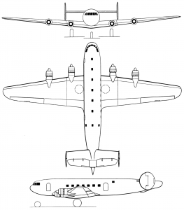
Developed to the specifications laid down by Aeravias Argentinas S.A. in late 1936 for a new long-range airliner the I.Ae 7 first flew during late 1937 and enter service in 1938. This is the biggest aircraft yet attempted in Argentina and it is technically equal to any type available form America or Europe. Ten have been ordered by Aeravias Argentinas S.A. off the drawing board. These aircraft will have the construction numbers C/N01001-C/N01010. Future developments may include a pressure-cabin for higher altitude flights. LAN-Chile is the first export user of the type.
Dimensions; span 32m; length 25m; wing area 1,300 sq ft; wing loading 32.5lb/sq ft
Structure: all-metal monocoque fuselage with I section fames and L section stringers with stressed light alloy covering, light alloy used for cantilever twin-tail construction and tailplane covering. Cantilever metal wing with three I section steel spars, hydraulically-activated all-metal split flaps and aluminium framed ailerons with aluminium covering. Twin rudders and elevators aluminium framed with aluminium covering. Retractable hydraulically-raised main undercarriage with single oleo-pneumatic legs with twin pneumatic brakes and a retractable castoring tail wheel
Weights: loaded (short haul) 42,000lbs
Powerplant: four 1,380hp Bristol Hercules IVC twin-row radial engines
Performance: max speed at 13,000ft 275mph; cruising speed at 60% rated power 225mph; range with full fuel load in still air at 50% rated power 1,700miles; stalling speed 70mph; payload of 500 miles 9,500lbs; payload for 1,700 miles 4,500lbs
Capacity: pilot and co-pilot in cockpit with navigator and radio-operator in a cabin behind, aft of this is a mail hold and galley, then the main compartment 9.75m long; 3m wide; 2.13m high seating 36 passengers four-abreast, aft is male and female toilets and baggage compartment, another is located under the forward cabin floor
Equipment: full controls and navigation equipment including receiver/transmitter, HF/DF set, Sperry autopilot and four rescue dinghies

FMA I.Ae 8
Designed as a three-seat touring aircraft for the export market.
Dimensions: span 10.2m; length 7.32m; wing area 16.8 sq m; wing loading 53kg/ sq m; power loading 7.4kg/hp
Structure: steel-tube fuselage truss with light alloy fuselage covering and fabric aft, light alloy used for tail construction and tailplane covering. Wooden wing with two spars, all-metal split flaps and wooden ailerons with fabric covering. Rudder and elevators aluminium framed with fabric covering. Fixed main undercarriage in spats with a non-retractable castoring tail wheel
Weights: empty 566kg, all-up weight 891kg
Powerplant: one 120hp de Havilland Gipsy Major
Performance: max speed 130mph; service ceiling 14700ft; landing speed 51mph; take-off run 200m; landing run 340m; range 447 miles
Capacity: pilot and two passengers in cabin
Equipment: full controls and navigation equipment including receiver/transmitter and Sperry autopilot


FMA I.Ae 9
Designed as a two-seat racing aircraft with a secondary mail plane role.
Dimensions: span 11m; length 7.17m; wing area 15.6 sq m; wing loading 77kg/ sq m; power loading 8.02kg/hp
Structure: steel-tube fuselage truss with forward fuselage light alloy fuselage covering with plywood aft of the firewall, light alloy used for tail and tailplane construction with fabric covering. Wooden wing with two spars with no flaps, wooden ailerons with fabric covering. Rudder and elevators aluminium framed with fabric covering. Simple manually-retractable main undercarriage with a non-retractable tail skid
Weights: empty 558kg, all-up weight 1,204kg
Powerplant: one 150hp Armstrong Siddeley Genet Major 1A seven-cylinder air-cooled radial
Performance: max speed 238mph; landing speed 58mph; take-off run 210m; range 1,860 miles
Capacity: pilot in cockpit and engineer/navigator or passenger in fuselage compartment with flush canopy
Equipment: full controls and navigation equipment including receiver/transmitter, HD/DF, Sperry autopilot and an extra fuel tank can be carried in the passenger/cargo compartment

This post has been edited 1 times, last edit by "Hood" (Jul 28th 2011, 11:27pm)

8

Sunday, March 6th 2011, 3:27pm

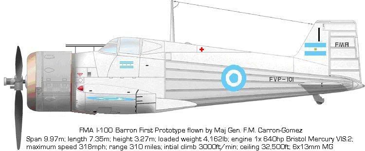
I-100 Barron


The FMA I-100 Barron was designed by Jack Northrop, James Smith McDonnell Jr and Luis Barron was a modern monoplane fighter. The two American designers were unemployed and recruited by FMA secretly FMA from early 1933 began service deliveries to all four fighter Regiments (144 aircraft). Exports were made to Atlantis (8), Brazil (264), Italy (8) and Siam.

Dimensions: span 9.97m; length 7.35m; height 3.27m; wing area 13.58 sq m; wing loading 28.06 lb per sq foot; power loading 6.5 hp per lb
Structure: Metal monocoque fuselage with flush countersunk rivets. Metal wing with steel spars, all-metal split flaps and wooden ailerons with fabric covering. Rudder and elevators wood framed with fabric covering.
Weights: loaded 4,162lb
Powerplant: one 640hp Bristol Mercury VIS.2 radial
Performance: Maximum speed 315mph; range 310miles, initial climb 3000 feet/min; service ceiling 32,500ft
Armament: four Browning 13mm machine guns (two in fuselage, four in wings)

FMA I-100A
Improved features, new 700hp radial, new reflector gunsight, new radio transmitter/receiver and streamlined canopy.
Argentina: 144 fighters in eight batches (18 aircraft each) to be delivered by Jan 1935. Construction numbers will be C/N09001-C/N16018.
Dimensions: span 9.97m; length 7.38m; height 3.27m; wing area 13.58 sq m; wing loading 28.74 lb per sq foot; power loading 6.13 hp per lb
Structure: Metal monocoque fuselage with flush countersunk rivets. Metal wing with steel spars, all-metal split flaps and wooden ailerons with fabric covering. Rudder and elevators wood framed with fabric covering.
Weights: loaded 4,297lb
Powerplant: one 700hp FMA RR-14-2 twin-row radial
Performance: Maximum speed 321mph; range 310miles, initial climb 3000 feet/min; service ceiling 32,500ft
Armament: six Browning 13mm machine guns (two in fuselage, four in wings)

FMA I-100C
Due to the shortage of various items, mainly machine guns the I-100C is armed with the 7.92mm FMG/M32 (the Lehky Kulomet ZB vz.30 7.92mm produced under licence) in a belt-fed form. Other equipment as I-100A but lower standard radio (receive only) and an extra fuel tank behind the engine below the oil tank. These were built by Tucan under licence.
Argentina: 72 fighters in four batches (18 aircraft each) to be delivered by July 1935. Construction numbers will be C/N17301-C/N20318.
Dimensions: span 9.97m; length 7.38m; height 3.27m; wing area 13.58 sq m; wing loading 28.04 lb per sq foot; power loading 0.16 hp per lb
Structure: Metal monocoque fuselage with flush countersunk rivets. Metal wing with steel spars, all-metal split flaps and wooden ailerons with fabric covering. Rudder and elevators wood framed with fabric covering.
Weights: loaded 4,182lb
Powerplant: one 700hp FMA RR-14-2 twin-row radial
Performance: Maximum speed 323mph; range 390miles, initial climb 3000 feet/min; service ceiling 32,500ft
Armament: four FMG/M32Ar 7.92mm machine guns (four in wings)
Equipment: full controls and navigation equipment including radio receiver and Sperry autopilot

FMA I-100D
This is a modified I-100A fighter with a ventral camera mounted in the fuselage just behind the cockpit. The two fuselage machine guns being removed to save weight. FMA has developed a special retrofit package with electrical lens heater etc. The camera is of British origin and all 24 conversions were carried out by service personnel during overhauls throughout early 1938.

9

Sunday, March 6th 2011, 3:29pm

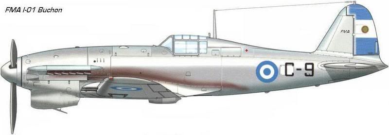
I-01 Buchon


The FMA I-01 Buchon has been designed by Luis Barron and his team to replace the I-100 and is heavily based on the CR.35 and Bf.109 of the recent Talons Contests. FMA began service deliveries to four fighter Regiments (144 aircraft) from early 1936.
Dimensions: span 10.05m; length 9.14; height 3.22m; wing area 176sq ft; wing loading 34.09 lb/sq ft; power loading 0.16 lb/hp
Structure: all-metal monocoque fuselage with I section fames and L section stringers with stressed light alloy covering, light alloy used for cantilever tail construction and tailplane covering. Cantilever metal wing with two steel spars, all-metal split flaps and aluminium framed ailerons with aluminium covering. Rudder and elevators aluminium framed with aluminium covering. Retractable hydraulically raised main undercarriage with single oleo-pneumatic legs with twin pneumatic brakes and a retractable castoring tail wheel
Weights: empty 4,796lbs, maximum take-off 6,000lbs
Powerplant: one 1000hp Spartan 1000 V-12 inline engine with supercharger, maximum sea level output to 10,000ft
Performance: max speed 334mph; service ceiling 33,000ft; rate of climb 2,471ft per minute at 1,500ft; range 526 miles full fuel load
Capacity: pilot in enclosed cockpit armoured windscreen and 8mm thick armoured bulkhead behind
Armament: four 13mm Browning HMG in wings, bomb racks can be fitted for light bombs
Equipment: full controls and navigation equipment including receiver/transmitter, reflector sight, Sperry autopilot, one camera can be fitted in radio compartment floor, one flare chute and one rescue dinghy

FMA I-01-II Buchon
Developed from the I-01 this improved variant has a new engine and other improved equipment based on war experience. An order for 144 aircraft was placed and have the batch numbers previously allocated to the cancelled I-01s, numbers C/N09001-C/N16018.
Dimensions: span 10.05m; length 9.14; height 3.22m; wing area 176sq ft; wing loading 35.22 lb/sq ft; power loading 0.20 lb/hp
Structure: all-metal monocoque fuselage with I section fames and L section stringers with stressed light alloy covering, light alloy used for cantilever tail construction and tailplane covering. Cantilever metal wing with two steel spars, all-metal split flaps and aluminium framed ailerons with aluminium covering. Rudder and elevators aluminium framed with aluminium covering. Retractable hydraulically raised main undercarriage with single oleo-pneumatic legs with twin pneumatic brakes and a retractable castoring tail wheel
Weights: empty 5,423lbs, maximum take-off 6,200lbs
Powerplant: one 1300hp Spartan 1300S V-12 inline engine with supercharger, maximum sea level output to 12,000ft
Performance: max speed 377mph; service ceiling 36,000ft; rate of climb 2,931ft per minute at 1,500ft; range 466 miles full fuel load
Capacity: pilot in enclosed cockpit armoured windscreen and 8mm thick armoured bulkhead behind
Armament: four 13mm Browning HMG in wings
Equipment: full controls and navigation equipment including receiver/transmitter, reflector sight, Sperry autopilot, one flare chute and one rescue dinghy

FMA I-01N Buchon
32 ordered by Chile for Q1/37.
In response to a specification for a carrier-based fighter Luis Barron developed a modified carrier fighter based on the FMA I-01 differing only in structural weights, addition of a rear fuselage fuel tank and carrier-operation gear. The Navy quickly turned down the I-01N in favour of Japanese fighters for both technical and political reasons. One surplus standard fighter was fitted with catapult spools and arrester gear in July 1936 and used for dummy deck landing trials. In late 1936 Chile ordered 32 I-01N fighters for delivery from February 1937. These aircraft have the construction numbers C/N17001-C/N17032
Dimensions: span 10.05m; length 9.14; height 3.22m; wing area 176sq ft; wing loading 35.79 lb/sq ft; power loading 0.15 lb/hp
Structure: all-metal monocoque fuselage with I section fames and L section stringers with stressed light alloy covering, light alloy used for cantilever tail construction and tailplane covering. Cantilever metal wing with two steel spars, all-metal split flaps and aluminium framed ailerons with aluminium covering. Rudder and elevators aluminium framed with aluminium covering. Retractable hydraulically raised main undercarriage with single oleo-pneumatic legs with twin pneumatic brakes and a retractable castoring tail wheel and catapult spools and retractable arrestor hook attached to the lower fuselage aft.
Weights: empty 5,234lbs, maximum take-off 6,500lbs
Powerplant: one 1000hp Spartan 1000 V-12 inline engine with supercharger, maximum sea level output to 10,000ft
Performance: max speed 322mph; service ceiling 31,000ft; rate of climb 2,0701ft per minute at 1,500ft; range 731 miles full fuel load
Capacity: pilot in enclosed cockpit armoured windscreen and 8mm thick armoured bulkhead behind
Armament: four 13mm Browning HMG in wings, one 250lb bomb on a ventral bomb rack under the fuselage
Equipment: full controls and navigation equipment including receiver/transmitter, reflector sight, Sperry autopilot, two flare chutes and one rescue dinghy

FMA I-01-IIB Buchon
Developed from the standard I-01-II this improved variant is for the dive-bomber/ fighter requirement with bomb-racks and dive-brakes. An order for 144 aircraft has been placed and these have the batch numbers C/N17001-C/N24018.
Dimensions: span 10.05m; length 9.14; height 3.22m; wing area 176sq ft; wing loading 39.7 lb/sq ft; power loading 0.18 lb/hp
Structure: all-metal monocoque fuselage with I section fames and L section stringers with stressed light alloy covering, light alloy used for cantilever tail construction and tailplane covering. Cantilever metal wing with two steel spars, all-metal split flaps and aluminium framed ailerons with aluminium covering with two hydraulic dive-brakes. Rudder and elevators aluminium framed with aluminium covering. Retractable hydraulically raised main undercarriage with single oleo-pneumatic legs with twin pneumatic brakes and a retractable castoring tail wheel
Weights: empty 5,569lbs, maximum take-off 7,000lbs
Powerplant: one 1300hp Spartan 1300S V-12 inline engine with supercharger, maximum sea level output to 12,000ft
Performance: max speed 371mph at 15,000ft; service ceiling 22,500ft; rate of climb 2,455ft per minute at 1,500ft; range 304 miles full fuel load
Capacity: pilot in enclosed cockpit armoured windscreen and 8mm thick armoured bulkhead behind
Armament: four 13mm Browning HMG in wings and ventral bomb rack for one 250kg bomb and wing racks for either four 50kg or ten 15kg bombs
Equipment: full controls and navigation equipment including receiver/transmitter, reflector sight, Sperry autopilot and one flare chute


FMA TI-01-IIB
On 9 December 1944, a prototype conversion of an I-01-IIB converted into a two-seat trainer was flown. The cockpit is moved forwards and behind is inserted another cockpit with reduced instrumentation and a blown canopy for an instructor. The bomb racks, armoured bulkhead and two machine-guns are removed. A gun-camera was added to the starboard wing leading edge. Performance is almost identical to the standard fighter.
From April 1945, IMPA began converting twenty-nine other airframes for the fighter training role.

10

Sunday, March 6th 2011, 3:34pm

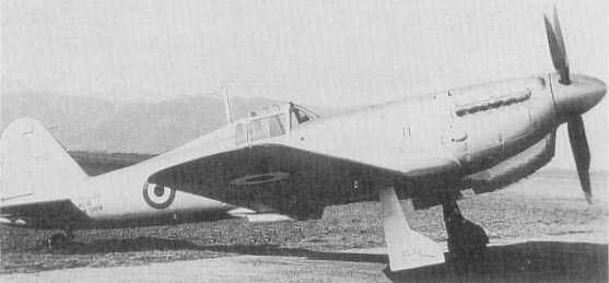
I-02 Pulqui


FMA I-02
Developed from scratch as a modern fighter heavily based on war experience and rectifying faults in the I-01 series. An order for 144 aircraft has been placed, construction numbers are C/N01001-C/N01144.
Dimensions: span 10.6m; length 10.3; height 3.42m; wing area 197sq ft; wing loading 38 lb/sq ft; power loading 0.17 lb/hp
Structure: all-metal monocoque fuselage with I section fames and L section stringers with stressed light alloy covering, light alloy used for cantilever tail construction and tailplane covering. Cantilever metal wing with two steel spars, all-metal split flaps and aluminium framed ailerons with aluminium covering. Rudder and elevators aluminium framed with aluminium covering. Retractable hydraulically raised main undercarriage with single oleo-pneumatic legs with twin pneumatic brakes and a retractable castoring tail wheel
Weights: empty 5,882lbs, maximum take-off 7,500lbs
Powerplant: one 1300hp Spartan 1300S V-12 inline engine with supercharger, maximum sea level output to 15,000ft
Performance: max speed 414mph at 15,000 feet; service ceiling 35,000ft; rate of climb 2,598ft per minute at 1,500ft; range 691 miles full fuel load
Capacity: pilot in enclosed cockpit armoured windscreen and 8mm thick armoured bulkhead behind
Armament: four 13mm Browning HMG in wings and a ventral bomb-rack for one 250-500lb bomb
Equipment: full controls and navigation equipment including receiver/transmitter, reflector sight, Sperry autopilot, flare chute and one rescue dinghy

FMA I-02R
This is a modified I-02 fighter with a ventral camera mounted in the rear. Two machine guns are removed to save weight. FMA has developed a special retrofit package with electrical lens heater etc. for the camera of British origin. All 24 conversions were carried out by service personnel during overhauls throughout early 1944.

FMA I-02II
FMA has begun work on a development of the I-02 fighter powered by the 1,500hp Spartan inline engine, which was the preferred choice for the original aircraft but lack of availablity curtailed this choice. An order for 144 has been placed and production should begin in 1941.
This is the planned definitive production type fitted with the Spartan 1,500hp V-12. An order for 144 aircraft has been placed with entry into service planned for late 1941. Construction numbers will be C/N01001-C/N01144.
Dimensions: span 10.6m; length 10.3; height 3.42m; wing area 197sq ft; wing loading 35.5 lb/sq ft; power loading 0.21 lb/hp
Structure: all-metal monocoque fuselage with I section fames and L section stringers with stressed light alloy covering, light alloy used for cantilever tail construction and tailplane covering. Cantilever metal wing with two steel spars, all-metal split flaps and aluminium framed ailerons with aluminium covering. Rudder and elevators aluminium framed with aluminium covering. Retractable hydraulically raised main undercarriage with single oleo-pneumatic legs with twin pneumatic brakes and a retractable castoring tail wheel. The cockpit windscreen is of 15mm thick armoured glass.
Weights: empty 6,017lbs, maximum take-off 7,500lbs
Powerplant: one 1500hp Spartan 1500S-SS V-12 inline engine with two-stage supercharger, maximum sea level output to 15,000ft
Performance: max speed 423mph at 15,000 feet; service ceiling 37,500ft; rate of climb 3,054 per minute at 1,500ft; range 664 miles full fuel load
Capacity: pilot in enclosed cockpit armoured windscreen and 8mm thick armoured bulkhead behind
Armament: four 13mm Browning HMG in wings and a ventral bomb-rack for one 250-500lb bomb
Equipment: full controls and navigation equipment including receiver/transmitter, reflector sight, Sperry autopilot and flare chute

FMA I-02III Pulqui
As a stop-gap until the new Gloster Meteor jet-fighters were delivered, in mid-1946 the Air Force agreed an order for 35 new-build aircraft with several improvements including a further developed Spartan V-12 engine with new supercharger, new gunsight and four Orkileon 20mm cannon replacing the machine-guns. The first entered service in January 1947. Construction numbers will be C/N01151-C/N01185.
Powerplant: one 1600hp Spartan 1500S-SP V-12 inline engine with modified two-stage supercharger, maximum sea level output to 16,000ft
Performance: max speed 431mph at 15,000 feet; service ceiling 38,500ft; rate of climb 3,062ft per minute at 1,500ft; range 975 miles full fuel load including two drop-tanks
Armament: four 20mm Orkileon cannon in wings and two underwing and one ventral bomb-rack for one 250-500lb bomb, 1,000lb maximum load, alternatively 8x 75mm RPs

FMA I-02N
This is an I-02II with Spartan developed folding wings and Atlantean arrestor gear fitted. Although labelled in Argentine service as an FMA all are in fact built by Spartan in Atlantis and FMA had very little to do with the development of the I-02N.
This carrier-based variant was developed entirely by Spartan and is built in Atlantis. The I-02N has a new folding wing of greater span but otherwise is based on the I-02II. An order for 54 aircraft has been placed with entry into service planned for late 1940.
Dimensions: span 11.2m; length 10.3; height 3.42m; wing area 195sq ft; wing loading 35.89 lb/sq ft; power loading 0.21 lb/hp
Structure: all-metal monocoque fuselage with I section fames and L section stringers with stressed light alloy covering, light alloy used for cantilever tail construction and tailplane covering. Cantilever metal wing with two steel spars, all-metal split flaps and aluminium framed ailerons with aluminium covering. Hydraulic wing folding with two hinges and locks on each wing. Rudder and elevators aluminium framed with aluminium covering. Retractable hydraulically raised main undercarriage with single oleo-pneumatic legs with twin pneumatic brakes and a retractable castoring tail wheel. A retractable arrestor hook is fitted near the tailwheel and there are four catapult attachment points on the lower fuselage and front spars in the wing roots. The cockpit windscreen is of 15mm thick armoured glass.
Weights: empty 6,204lbs, maximum take-off 7,500lbs
Powerplant: one 1500hp Spartan 1500S-SS V-12 inline engine with two-stage supercharger, maximum sea level output to 15,000ft
Performance: max speed 423mph at 15,000 feet; service ceiling 37,500ft; rate of climb 3,054 per minute at 1,500ft; range 664 miles full fuel load
Capacity: pilot in enclosed cockpit armoured windscreen and 8mm thick armoured bulkhead behind
Armament: four 13mm Browning HMG in wings and a ventral bomb-rack for one 250-500lb bomb
Equipment: full controls and navigation equipment including receiver/transmitter, reflector sight, Sperry autopilot, flare chute and dingy

FMA I-02IIIN
A naval version of the I-02III with the folding wings and strengthened fuselage with arrestor gear of the I-02N. 48 were ordered in July 1947 and deliveries began in January 1948. Construction numbers are C/N01186-C/N01234.
Powerplant: one 1600hp Spartan 1500S-SP V-12 inline engine with modified two-stage supercharger, maximum sea level output to 16,000ft
Performance: max speed 431mph at 15,000 feet; service ceiling 38,500ft; rate of climb 3,062ft per minute at 1,500ft; range 975 miles full fuel load including two drop-tanks
Armament: four 13mm Browning HMG in wings and one ventral bomb-rack for one 250-500lb bomb, and underwing mounts for 8x 75mm RPs

This post has been edited 2 times, last edit by "Hood" (Jun 8th 2013, 3:05pm)

11

Sunday, March 6th 2011, 3:35pm

I.Ae. 22 DL


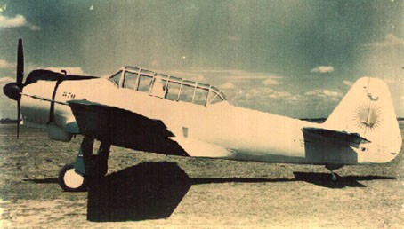
I.Ae.22 DL
Designed from early 1940 and based on the overall layout of the North American NA-16 trainer the I.Ae.22 DL is designed to be the future basic/ advanced and armament trainer of the FAA. It is the first Argentine aircraft designed around the new 450hp El Gaucho 9-cylinder radial. A batch of 100 DLs have been ordered for the Fuerza Aerea Argentina and the Commando de Aviacion Naval Argentina (split 75/25). In 1943 another batch of 100 was ordered. The I.Ae.22C export version has a British engine.

Dimensions: span 12.6m; length 9.2m; height 2.2m; wing area 23.19 sq m; wing loading 96kg/ sq m; power loading 5.28kg/hp
Structure: wooden framed fuselage with light alloy forward fuselage covering with plywood aft of the firewall, light alloy used for tail and tailplane construction with fabric covering. Low position wing with light alloy spars and stringers with aluminium framed ailerons with fabric covering. Rudder and elevators aluminium framed with fabric covering. Retractable main undercarriage with hydraulic brakes and a non-retractable tail wheel.
Weights: empty 1,550kg; max weight 2,220kg
Powerplant: one 450hp El Gaucho 9-cylinder radial with a Hamilton Standard 2M-D-30 propeller or a 475hp Armstrong Siddeley Cheetah 25 radial or a 450hp Alvis Leonides I/ 520hp Leonides II (as I.Ae 22C)
Performance: max speed 180mph; cruising speed 161mph; range 680 miles and service ceiling 17,060ft
Capacity: pupil and instructor seated in tandem in an enclosed cockpit
Equipment: full controls and navigation equipment including a radio receiver/transmitter and HF/DF, two 7.92mm MG (with 450 rounds each) or three 15-50kg bombs can be fitted for armament training [or 6x 75mm rockets].

This post has been edited 2 times, last edit by "Hood" (Nov 18th 2012, 12:08pm)

12

Saturday, November 17th 2012, 2:11pm

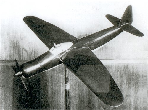
I.Ae 23 Jaguar


I.Ae 23 Jaguar
In early 1940 FMA brought the plans, research data and jigs of the cancelled Ju-187 dive-bomber project from Junkers when the Argentine Air Staff began looking at modern dive-bomber studies. FMA had a large task on its hands, translating the documentation in Spanish, understanding it and completing wind tunnel testing and structural testing. A new engine type had to be found and integrated and of course all the equipment would be different and the construction methods would need to be simplified.
The I.Ae 23 dive bomber is armed with two forward-firing 13mm Browning HMGs in the inner wings and is capable of carrying a bombload of up to 1000 kg internally, with up to 500 kg carried externally under the wings (though using all the load capacity requires reducing the range to only 400 nm, so the normal load is a 500-1000 kg bomb carried internally). It is equipped with cockpit and engine armour plating along with self-sealing fuel tanks. The wide-track inward-retracting main landing gear is housed in the inner wings. Later developments will include provision for a large 900 litre droppable internal fuel tank to increase the aircraft's range and a naval variant. This was planned by Junkers and formed the basis of the Ju-187 basic design so little work is needed to restore the folding wings and arrestor hook. First flight 3rd March 1942, second prototype flew in June and production began November.

Dimensions: span 13.7m; length 11.4m; height 3.9m; power loading 3.62 kg/hp
Structure: all-metal monocoque fuselage with H section fames and T section stringers with stressed light alloy covering, light alloy used for cantilever tail construction and tailplane covering. The cockpit is armoured and an armoured windscreen is also fitted. Cantilever metal wing with two steel spars, all-metal split flaps and aluminium framed ailerons with aluminium covering. Slatted pneumatically-operated dive brakes are fitted near the trailing edge of the landing flaps. Rudder and elevators aluminium framed with aluminium covering. Retractable hydraulically raised main undercarriage with single oleo-pneumatic legs with twin pneumatic brakes and a retractable tail wheel. Provision for an arrestor hook.
Weights: empty 4,139kg; max weight 6,531kg
Powerplant: one 1,800hp Austral Incitatus 2W-11 radial engine (1,650hp at 16,900ft / 5,150m; 2,030hp with water injection at sea level)
Performance: max speed 350mph; cruising speed 260mph; range 1,612 miles with 2,080 lb payload, rate of climb 1,721 ft/min and service ceiling 31,000ft
Capacity: pilot in an enclosed cockpit
Equipment: full controls and navigation equipment including a radio receiver/transmitter and HF/DF, reflector sight, Sperry autopilot, flare chute and dingy and provision for one ventral camera.

13

Sunday, November 18th 2012, 12:05pm

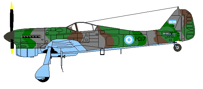
I.Ae 24 B-01 Calquin


I.Ae 24 Calquin (Golden Eagle)
Designed 1942 as a fast light bomber, might use Merlin or comparable inline engines as I.Ae 28. First flight June 5 1943. In July 1943, 144 were ordered but with the success of the I.Ae.28 these orders were cut to just 72. Deliveries began in January 1944.
Dimensions: span 16.3m; length 12m; height 3.4m; wing area 38 sq m; wing loading 189kg/ sq m; power loading 3.42kg/hp
Structure: wooden monocoque fuselage plywood covering developed by Instituto Aerotechico and Entel. The fuselage is constructed as two separate halves which are subsequently joined together. Wooden tail and tailplane construction with plywood covering (the plywood is entirely produced by the Instituto Aerotécnico). Rudder and elevators wooden framed with fabric covering. Mid position wing with two wooden carry-through spars and stringers wooden framed ailerons with fabric covering, wooden slotted flaps and two landing flaps. Retractable main undercarriage with hydraulic brakes and twin oil-air shock absorbers on each leg and a retractable tail wheel.
Weights: empty 5,340kg; max weight 8,164kg and payload 1860kg
Powerplant: 1200hp Ripon R-1200-010A supercharged radial engines with Hamilton Standard Hydromatic 23-E-50 propellers
Performance: max speed 273mph; cruising speed 236mph; range 708 miles; rate of climb 2,460ft/min and service ceiling 32,800ft
Capacity: pilot and navigator/ bomb-aimer seated side-by-side in an enclosed cockpit with ventral door
Armament: Four 13mm Browning HMG (capability to be replaced by 20mm cannon) in lower nose, bomb bay for 800kg bombload and 12x 75mm rockets underwing
Equipment: full controls and navigation equipment including a radio receiver/transmitter, HF/DF set, naval co-operation beacon and Sperry autopilot, two cameras can be fitted in cabin floor, one flare chute, two rescue dinghies and mechanical bombsight

This post has been edited 4 times, last edit by "Hood" (Jun 8th 2013, 5:41pm)


14

Saturday, June 8th 2013, 3:09pm

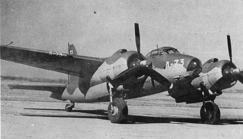
I.Ae 28 B-02 Calquin


I.Ae 28 B-02 Calquin
The second I.Ae.24 prototype was converted with two 1,760hp Rolls-Royce Merlin XII V-12 engines during July 1944 and first flew with these new engines on 24 October 1944. Performance tests went well and orders for 144 were soon placed and entry into service began during the summer of 1945.
Dimensions: span 16.3m; length 12m; height 3.4m; wing area 38 sq m; wing loading 249kg/ sq m; power loading 2.68kg/hp
Structure: wooden monocoque fuselage plywood covering developed by Instituto Aerotechico and Entel. The fuselage is constructed as two separate halves which are subsequently joined together. Wooden tail and tailplane construction with plywood covering (the plywood is entirely produced by the Instituto Aerotécnico). Rudder and elevators wooden framed with fabric covering. Mid position wing with two wooden carry-through spars and stringers wooden framed ailerons with fabric covering, wooden slotted flaps and two landing flaps. Retractable main undercarriage with hydraulic brakes and twin oil-air shock absorbers on each leg and a retractable tail wheel.
Weights: empty 5,840kg; max weight 9,464kg and payload 3500kg
Powerplant: two 1,760hp Rolls-Royce Merlin XII V-12 engines with de Havilland 4/4400/5 3.66m diameter four-bladed hydromatic constant-speed control propellers with auto-feathering and clocked rotation
Performance: max speed 366mph; cruising speed 310mph; range 1,105 miles; rate of climb 2,850ft/min and service ceiling 33,000ft
Capacity: pilot and navigator/ bomb-aimer seated side-by-side in an enclosed cockpit with ventral door
Armament: four 20mm Orkileon in lower nose, bomb bay for 1000kg bombload and 12x 75mm rockets underwing
Equipment: full controls and navigation equipment including a radio receiver/transmitter, HF/DF set, naval co-operation beacon and Sperry autopilot, two cameras can be fitted in cabin floor, one flare chute, two rescue dinghies and mechanical bombsight

15

Thursday, March 5th 2015, 9:58pm

I.Ae.30 I-03 Ñancú


Designed by Luis Barron and his team during 1944 to meet the need for a long-range fighter. The I.Ae. 30 is an all-metal fighter, powered by two Rolls-Royce Merlin V-12 engines, a decision made given the lack of suitable Spartan engines. The armament is designed for both attacking enemy bombers and ground attack. By the end of 1943, a contract was received for three prototypes. On 9 June 1945 the first prototype was ready for ground tests and on 17 July 1945, took to the air for the first time, piloted by Captain de Aero Edmundo Osvaldo Weiss. Trials proved that the I.Ae.30 possessed good flying characteristics and fully met the performance specifications. During a cross country flight, from Córdoba to Bahia Blanca, the Ñancú reached a level speed of 780 km/h, setting a new piston engined speed record in South America. In mid-1944 144 production aircraft were ordered as the I-03 Ñancú.

Dimensions: span 15m; length 11.52m; height 5.12m; wing area 35.32 sq m; wing loading 215 kg/m² (44 lb/sq ft); power loading 0.353 kW/kg (0.215 hp/lb)
Structure: light-alloy monocoque fuselage and gradually further aft becomes triangular in cross-section. Light alloy cantilever tailplane (incidence changeable in flight) and fin construction. Rudder and elevators aluminium framed with aluminium covering. Mid position wing with steel carry-through spars and with one-piece stringers, the wing has split flaps with a rod driving system with the motor located on the rear spar, three-piece ailerons and leading edge radiators between the nacelles and fuselage. Retractable main undercarriage (wheel rotates on shaft diameter while retracting backwards and up) with Dunlop hydraulic brakes and a retractable tail wheel.
Weights: empty 6,208kg; max weight 7,600kg
Powerplant: two 1,760hp Rolls-Royce Merlin XII V-12 engines with de Havilland 4/4400/5 3.66m diameter four-bladed hydromatic constant-speed control propellers with auto-feathering and ‘clocked’ rotation
Performance: max speed 740 km/h (460 mph); cruising speed 500 km/h (311 mph); range 2,700 km (1,678 miles); endurance 5 hrs 25 min and service ceiling 8,000 m (26,247 ft)
Armament: six Orkileon 20mm cannon in the lower fuselage and a ventral bomb rack for one 500kg or 250kg bomb and 10x 75mm rockets underwing
Equipment: full controls and navigation equipment including a radio receiver/transmitter, HF/DF set, naval co-operation beacon and Sperry autopilot, one camera can be fitted in the rear fuselage, one flare chute, rescue dinghy and stabilised reflector gunsight

16

Thursday, March 5th 2015, 10:00pm

I.Ae.31 Colibri


Designed in 1945, and built by, the H. Goberna factory at Alto Alberdi, Cordoba as a civil light plane and aerobatics plane. Three were purchased by the National Aeronautics School in 1946.
Dimensions: span 10.3m; length 7.95m; wing area 16 sq m
Structure: steel-framed fuselage with light alloy forward fuselage covering with plywood aft of the firewall, light alloy used for tail and tailplane construction with fabric covering. Rudder and elevators wood framed with fabric covering. Low position wooden wing with plywood covering and wood framed ailerons with fabric covering. Fixed main undercarriage with oil-pneumatic shock absorbers and hydraulic brakes and a non-retractable tail wheel.
Weights: empty 635kg; gross weight 916kg
Powerplant: one 155hp Blackburn Cirrus Major with a de Havilland two-blade variable-pitch propeller
Performance: max speed 150mph; endurance 1hr 50mins and service ceiling 21,300ft
Capacity: pupil and instructor seated in tandem in an enclosed cockpit
Equipment: dual controls and full navigation equipment including a radio receiver/transmitter.

17

Thursday, March 5th 2015, 10:01pm

I.Ae. 32 Chingolo


Designed in 1946 and very similar to the I.Ae.31, but with a high back fuselage, the prototype was built the same year at the Mario Vicente workshops in Córdoba.
Dimensions: span 10.70m; length 8.12m; height 2.18m; wing area 16.50 sq m
Structure: steel-framed fuselage with light alloy covered forward fuselage and fabric covering aft, light alloy used for tail and tailplane construction with fabric covering. Rudder and elevators wood framed with fabric covering. Low position wooden wing with plywood covering and wood framed ailerons with fabric covering. Fixed main undercarriage with oil-pneumatic shock absorbers and hydraulic brakes and a non-retractable tail wheel.
Weights: empty 750kg; gross weight 981kg; payload 231kg; wing loading 9.45kg/m2
Powerplant: one 155hp Blackburn Cirrus Major with a de Havilland two-blade variable-pitch propeller
Performance: max speed 230km/h (142mph); endurance 1hr 40mins and service ceiling 5180m (16,995ft)
Capacity: pupil and instructor seated in tandem in an enclosed cockpit
Equipment: dual controls and full navigation equipment including a radio receiver/transmitter.

18

Friday, March 31st 2017, 3:11pm

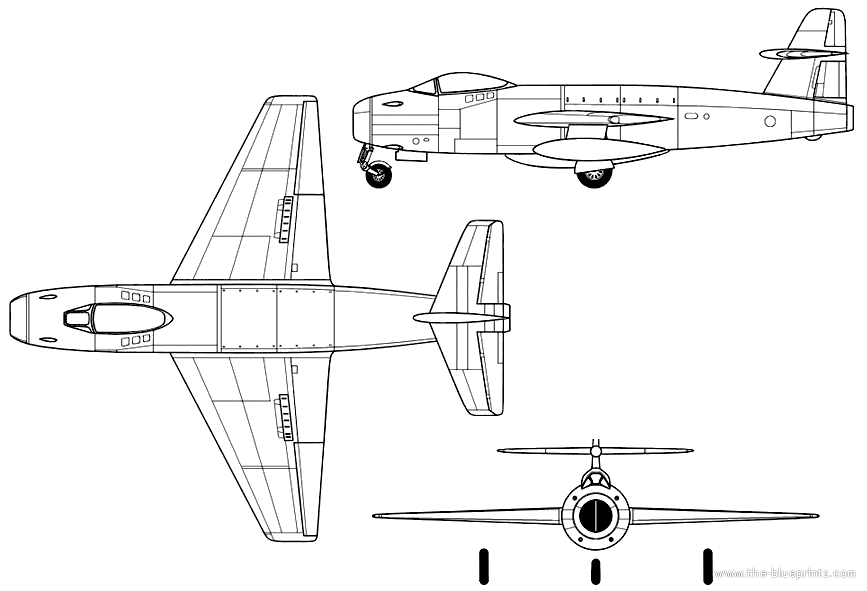
Gloster AXP-1001 / FMA I-05 Pulqui III


In 1946 Argentina sent a mission to Britain and negotiations saw an order for 100 Gloster Meteor F.Mk.IV fighters and for Gloster to co-operate with FMA engineers on the design of a new fighter. Argentina sent thirty FMA engineers to Hucclecote in September 1946. The new fighter was to have a Rolls-Royce engine and be delivered within thirty months and FMA had the option of purchasing the manufacturing rights. The initial contract signed in July 1946 was for three prototypes. Based on Gloster designs for jet fighters the design work moved along quickly and the mock-up was inspected during September 1947 and by then construction on the prototypes was underway. The design was basic with a nose intake, the cannon being mounted around the nose, a mid-set tailplane was fitted and the wings had moderate sweep of 20 degrees. Internal fuel capacity was 470 gallons. The first prototype made its first flight following taxi trials on 14 July 1948. The second followed on 22 March 1949 and the third prototype, which was shipped to Argentina and reassembled there, made its first flight on 16 June 1949. The third prototype and all production aircraft were fitted with Nene III engines rather than the Nene IIs fitted to the earlier prototypes. During February 1949 the manufacturing rights were acquired by FMA and tooling began the following month. The first of 160 production aircraft made its maiden flight on 26 August 1949 and the first batch of aircraft were handed to the Argentine Air Force in January 1950.

Dimensions; 38/ 41.9/ 14.10/ 360 sq ft; 1x 5,000lb Rolls-Royce RB.41 Nene III; max speed 600mph at sea level; range 1,000 miles with maximum external fuel; sea level rate of climb 6,000ft/min; service ceiling 40,000ft; all-up weight 14,250lb and overload weight 18,700lb. Armament: 4x 20mm Orkileon FFB cannon and 2x 500kg bombs or 12x 75mm rockets underwing. Two underwing 100 or 200 gallon drop tanks and one 195 gallon ventral tank can be fitted.

19

Sunday, March 22nd 2020, 11:49am

I.Ae. 29


This project for a single-seat advanced jet-powered conversion trainer began in 1948 using experience gained in helping Gloster develop the I-05 Pulqui III. The design is aerodynamically sleek with two lateral intakes for the single turbojet engine and a conventional straight wing for good controllability. The first prototype made its maiden flight on 28 August 1949. Following trials the Air Force took delivery of 50 production aircraft from July 1951.

Wingspan: 9.50m
Length: 9.20m
Height: 3.40m
Wing area: 18.70 m2
Wing loading: 179kg/m
Empty Weight: 2250kg (4,960lb)
Maximum take-off weight: 3150kg (6,944lb)
Powerplant: 1x 3,500lb Rolls-Royce Derwent V turbojet
Maximum speed: 800km/h (497mph)
Cruising speed: 630km/h (391mph)
Landing speed: 170km/h (105mph)
Take-off run: 660m
Service ceiling: 14000m (45,930ft)
Absolute ceiling: 15600m (51,180ft)
Endurance 1.5 hours
Range: 900km (560 miles)
Armament: 2x nose-mounted 20mm Orkileon FFB cannon and provision for 2x 50kg bombs or 8x 75mm rockets underwing.